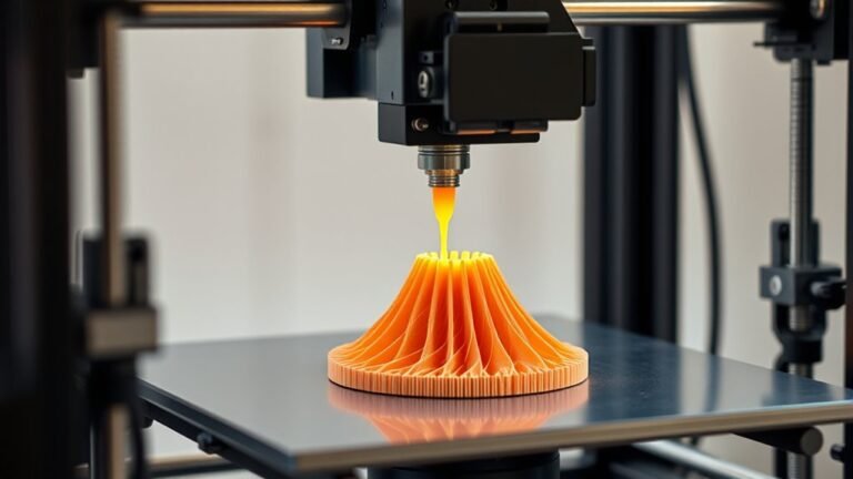
How Do You Make 3D Printer Files in 10 Easy Steps
To make 3D printer files in 10 easy steps, start by sketching your concept to visualize ideas.
Picking the right software, like Fusion 360, is key to getting things moving.
Set up your workspace with the correct units to keep everything accurate from the get-go.
Next, create reference dimensions to scale your design properly.
Import your sketches into the software to begin modeling.
Use tools like extrude, revolve, or loft to build your parts with precision.
Organize your components so you can easily make edits as you go.
When your design is ready, export it as an STL file.
Finally, slice the STL file and prepare your 3D printer to start the job.
You can explore each step in more detail next, and soon you’ll be creating awesome 3D prints with confidence!
Key Takeaways
- Start with a hand sketch to explore your design and define proportions before moving to CAD modeling. This helps you get your ideas down quickly and see what works.
- Import and scale your concept sketch accurately in CAD using reference lines and canvas tools. It makes sure your design stays true to your vision.
- Create fully constrained 2D sketches in CAD and use Extrude, Revolve, or Loft to build 3D solid parts. These tools bring your sketches to life in three dimensions.
- Organize your design into separate components for easier editing and assembly management. It keeps everything neat and makes changes simpler.
- Export finalized parts as high-refinement STL files, then import them into slicer software for printing setup. This step prepares your model for the actual 3D printing process.
Sketch Your Concept to Visualize Ideas
Before you dive into detailed 3D modeling, start by sketching your concept to visualize your ideas clearly. Make a simple hand sketch to explore the overall shape and how pieces might fit together—it doesn’t need to be perfect.
Create a new “Sketch 0” as a template or background so you can overlay fresh idea sketches without losing your reference proportions. Next, draw a separate motion or study sketch to decide what kind of movement your object requires, like sliding or pivoting. This will help guide your design.
Finally, turn your best concept into a final design sketch that clearly shows components and assembly order. Make sure to keep these sketches handy for when you’re ready to import them into CAD for scaling and extrusion.
Choose Software and Set Up Your 3D Modeling Workspace
When selecting software for your 3D modeling project, consider your design goals carefully. Autodesk Fusion 360 suits those who prefer sketch-to-solid workflows, while Blender offers powerful features but demands a steeper learning curve. FreeCAD provides parametric options that can be very handy.
Once you pick software, start a new project and set the correct units to match your design needs. In Fusion 360, use the Origin and vantage point views to keep orientation consistent. It really helps to stay organized.
Also, organize your workspace browser by grouping sketches, bodies, and construction elements. This way, you can manage complexity as your model grows without getting overwhelmed.
| Software | Best For |
|---|---|
| Fusion 360 | Sketch-to-solid design |
| Blender | Advanced features |
| FreeCAD | Parametric modeling |
Create Reference Dimensions for Accurate Scaling
To make sure your 3D model matches real-world dimensions, start by creating a reference line with a known length in your chosen units. Begin a new file and set your modeling units early to keep everything consistent.
Use the Sketch command to draw this reference line on your sketch plane, choosing a length that fits comfortably within your printer’s build volume. Later, when you insert your JPG concept sketch using the Canvas command, adjust its position and scale by linking it to this reference line.
This ensures your image scales precisely. Finally, check in the Project browser that your canvas aligns with the origin and the intended component center before moving on to modeling.
Accurate reference dimensions prevent scaling errors and set a solid foundation for your 3D print. It really helps keep everything on track as you move forward.
Import Sketches Into Fusion 360 for Modeling
After setting up your reference dimensions, you can bring your idea to life by importing your sketch into Fusion 360. Start by inserting your sketch as a .jpg canvas onto a chosen sketch plane using the Insert Canvas tool. Make sure you’ve set your project units first to prevent scaling issues.
Then, adjust and position the canvas precisely by aligning it with your reference line of known length.
Follow these steps to import effectively:
- Set project units (imperial or metric) before importing.
- Use Insert Canvas to add your sketch image.
- Scale the canvas by referencing your predefined dimension line.
- Organize your canvas and sketches in the Project Browser for easy access.
This process ensures your imported sketch matches your intended size perfectly. Just take your time with the alignment, and you’ll be all set!
Create Parts With Extrude, Revolve, and Loft Commands
Start by using the Extrude command to turn your sketches into solid shapes. Make sure to center symmetrical parts around the origin.
When your design revolves around an axis, use Revolve to create smooth, cylindrical forms. It’s a great way to get those rounded shapes just right.
For complex shapes that blend multiple profiles, Loft helps you connect sketches on different planes seamlessly. It really makes designing intricate parts easier and more precise.
Extrude Command Techniques
When you create parts in Fusion 360, mastering the Extrude command lets you transform a fully constrained sketch into a precise 3D solid or cut. You do this by setting the operation to Join or Cut and specifying the exact distance.
You can control thickness accurately and even maintain symmetry by extruding half the thickness on each side of the origin. It’s a great way to keep your design balanced.
Here are key Extrude command techniques to try:
- Start with a fully constrained sketch on your chosen plane. This gives you a solid base to work from.
- Set the operation to Join to add material or Cut to remove it. It’s simple but powerful.
- Use exact distances for precision—like 0.125 in on each side for centered thickness. Precision is everything here.
- Sketch on offset planes and extrude through bodies to create complex features. This opens up a lot of creative possibilities.
These steps ensure your parts are accurate and ready for 3D printing. Give them a try and see how your designs improve!
Revolve and Loft Methods
Although the Extrude command is great for adding thickness, you’ll rely on Revolve and Loft to create smooth, complex shapes that aren’t just straight pulls. Use Revolve to spin a closed profile around an axis—usually a construction line or origin centerline—for symmetrical round parts.
Make sure your sketch includes a clear axis reference and set the rotation angle. Loft helps you blend shapes by shifting between two or more sketches placed on offset planes.
Select profiles carefully to control the flow and twist.
| Command | Purpose | Key Tip |
|---|---|---|
| Extrude | Add thickness to a profile | Start your part design here |
| Revolve | Create round, symmetrical parts | Use a clear axis reference |
| Loft | Smoothly shifting shapes | Place profiles on separate planes |
| Revolve | Control angle of rotation | Full 360° or partial rotation |
| Loft | Blend multiple profiles | Select profile order carefully |
Shape Your 3D Print Parts With Additive and Subtractive Modeling
You’ll start shaping your 3D parts by adding material with additive modeling, like extruding new features from existing solids. Then, use subtractive methods to remove material by extruding sketches through your part.
Combining these techniques with multiple sketches and features helps you create complex, precise designs. It’s a great way to get exactly the shape you want without much hassle.
Additive Modeling Techniques
Since additive modeling builds parts layer by layer, you’ll start by sketching on a plane in Fusion 360 and use the Extrude tool to turn your sketch into a solid body. Often, you’ll extrude symmetrically about the origin to keep the part centered.
To stay organized, use Create Component for each part and activate it before extruding. For more complex shapes, tools like Revolve, Sweep, or Loft come in handy, but Extrude usually does the job for simple parts.
Here’s how to get started:
- Sketch on a plane and use Extrude to build solids.
- Create and activate components to organize parts.
- Use Revolve, Sweep, or Loft for complex shapes.
- Export finished components as STL for printing.
Subtractive Modeling Methods
To shape your 3D print parts with subtractive modeling in Fusion 360, start by creating a solid body through additive methods like Extrude. Next, sketch the profile you want to remove and use Extrude again, selecting the cut option to subtract material from the solid.
For more precise cuts, create an Offset Plane at a set distance from an existing surface, sketch on it, then extrude to cut. Keep your workflow organized by modeling each part as its own Component and managing sketches and bodies in the browser, so additive and subtractive steps stay clear.
When you finish shaping, export your part as an STL mesh via Save as Mesh. Just make sure to choose the right units and refinement before slicing for 3D printing.
Combining Sketches And Features
When combining sketches and features in Fusion 360, start by creating a 2D sketch on a selected plane and use Extrude to form a solid body. For symmetric parts, extrude half the thickness on each side of the origin to keep your design centered.
You can combine multiple sketches by adding Offset Planes and using extrude-through to subtract material, carving out features. It helps to organize your work by creating components for each part and managing sketches, origins, and canvases in the browser.
- Use Extrude for basic additive shapes.
- Extrude symmetrically to maintain alignment.
- Subtract with extrude-through on offset planes.
- Employ components to keep parts organized and ready for assembly.
This approach blends additive and subtractive modeling for precise, complex 3D prints. It’s a neat way to get detailed results without losing track of your design.
Organize Components for Easy Editing and Assembly
Organizing your components thoughtfully in Fusion 360 lets you edit each part individually without disrupting the rest of your assembly. Start by creating separate components for each part, ensuring you activate the correct component before sketching or extruding.
Keep your reference sketch visible in the root model to guide your design. This way, you always have a consistent point of reference while working on different parts.
Use the Project Browser to group and name components clearly, including Origin, Joints, Bodies, Canvases, Sketches, and Construction. It really helps keep things tidy and easy to navigate.
Draw sketches on intended or offset planes. Using offset planes can give you more precision and flexibility in your designs.
When using extrude-through subtraction, be careful to select the correct body or component. Doing this helps maintain clean edits without accidentally affecting other parts.
| Task | Tool/Feature | Tip |
|---|---|---|
| Component creation | Components panel | Separate parts for independent edits |
| Reference sketch | Root model | Keep visible for consistent guidance |
| Organization | Project Browser | Group and name for easy navigation |
| Sketching | Planes | Use offset planes for precise sketches |
| Editing | Extrude tools | Select correct body/component before subtracting |
Check and Export Your Model as an STL File for 3D Printing
Here’s how to check and export your model properly:
First, confirm you’ve selected the right component or body in your design workspace. This step is super important to avoid exporting the wrong part.
Next, in the export dialog, set the units to metric or your preferred system. This helps keep the scaling accurate.
Keep the file type as STL and select a high refinement. Doing this will give you smoother surfaces on your print.
If your model has multiple parts, make sure to export all necessary components together. That way, you get a complete assembly without missing anything.
After exporting, always open the STL in your slicer. It’s a quick way to verify the scale and geometry before printing.
Prepare and Slice Your 3D Print File
After exporting your model as an STL file, the next step is to prepare it for printing by slicing it into layers your 3D printer can understand. Open PrusaSlicer and select the exact printer profile, like the Prusa i3 MK3, so it uses the right build dimensions and toolhead settings.
Import your STL file, then choose your filament type, such as 1.75mm PLA. Adjust print quality to balance strength and detail based on your needs.
Set support options carefully—Automatic supports, Build Plate Only, or Support Enforcers—depending on whether your model has overhangs. When you’re ready, click “Slice Now” to generate the layer toolpaths and get an estimated print time and filament usage.
This process creates the G-code your printer will follow to build your model. It’s pretty straightforward once you get the hang of it!
Transfer G-Code and Start Your 3D Print Job
Follow these steps to smoothly begin printing:
First, double-check your printer model and filament settings before exporting the G-code. It’s a small step that saves a lot of headaches later.
Next, insert the SD card into your powered-on printer. Then, navigate to Print from SD and select your file.
Keep an eye on those initial layers. If you spot any issues, don’t hesitate to pause and adjust as needed.
Frequently Asked Questions
How Do I Create My Own STL Files for 3D Printing?
You create your own STL files by designing your part in CAD software like Fusion 360. Then, you organize the components to make sure everything fits together.
After that, you export the model as an STL file. It’s pretty straightforward!
Finally, you load the STL file into a slicer. This prepares it for 3D printing, setting up things like layers and supports. Easy, right?
What Are the Basic Steps of 3D Printing?
You design your 3D model and export it as an STL file. Then, you import it into a slicer to prepare it for printing.
Next, you generate the G-code, which tells your printer exactly how to create the object. After that, you transfer the G-code to your printer.
Finally, you start printing and keep an eye on the first layers. This helps ensure proper adhesion and smooth material flow.
What Files to Print on a 3D Printer?
Imagine your design coming to life—what files do you need? You’ll print STL or OBJ files, as they hold the 3D shape.
Export these from your design software, then slice to create printer-ready G-code.
It’s pretty straightforward once you get the hang of it! Just make sure your file is clean and error-free before slicing.
Is STL or Step Better for 3D Printing?
You’ll want to use STL for 3D printing since slicers read it directly as a mesh for toolpaths. It’s basically the go-to format when you’re ready to print.
Keep STEP files for editing and design changes. Then, when you’re set, just export STL for reliable printing every time. Makes the whole process smoother!
Conclusion
Creating 3D printer files is like planting a garden: you start with a simple seed—your sketch—then nurture it with the right tools and careful steps.
As you shape and organize your design, it grows into a detailed blueprint ready to bloom. When you export and print, you watch your idea blossom into a tangible creation.
Just like tending a garden, patience and care turn your vision into something real and beautiful. By following these steps, you can create precise and detailed 3D printer files that bring your ideas to life.
With the right software and a bit of practice, designing 3D models becomes easier and more enjoyable. In the end, your 3D printer files serve as the perfect bridge between imagination and reality, helping you produce unique, high-quality prints every time.