How Does a 3D Printer Know What to Print?
When you give a 3D printer a digital model, it first converts that file into thin layers using slicer software. This slicer generates precise G-code, which tells the printer’s motors and extruder exactly where to move and deposit material layer by layer.
Support structures and print orientation guide stable building. Your printer follows these instructions to shape your object from the ground up.
Keep going, and you’ll uncover how each step works together to bring your design to life. It’s pretty cool how these instructions transform a digital idea into a real, physical object—layer by layer!
Key Takeaways
- A 3D printer uses a digital 3D model file (like an STL or OBJ) that defines the exact shape it needs to print.
- Then, slicer software steps in to convert that model into layered toolpaths. It also generates G-code instructions that the printer can understand.
- G-code is pretty detailed. It includes exact coordinates, how much material to extrude, and the temperatures needed to guide the printer’s movements and material deposition.
- The printer’s firmware reads this G-code line by line. This is how it controls stepper motors, extruders, and other hardware parts.
- Plus, the instructions also include support structures and print orientation. These help keep the print stable and ensure good quality while printing.
What Is a 3D Printable Digital Model?
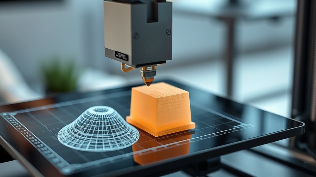
A 3D printable digital model is a precise, watertight 3D mesh or CAD file—usually saved as STL, OBJ, or 3MF—that defines the exact shape your printer will create.
A 3D printable model is a precise, watertight mesh or CAD file defining the exact shape for printing.
When you use an STL file, it represents surfaces with millions of tiny triangles, forming a manifold mesh without holes or non-manifold edges.
You must make certain your 3D printable model has no mesh errors like inverted normals, or your slicer may fail or generate incorrect toolpaths.
The slicer translates your model into G-code, guiding the printer layer by layer.
It’s critical to verify scale and units, as slicers interpret dimensions literally—mixing millimeters and inches can cause incorrect print sizes.
This precise preparation makes successful printing more likely.
Converting CAD and 3D Scans Into Printable Files
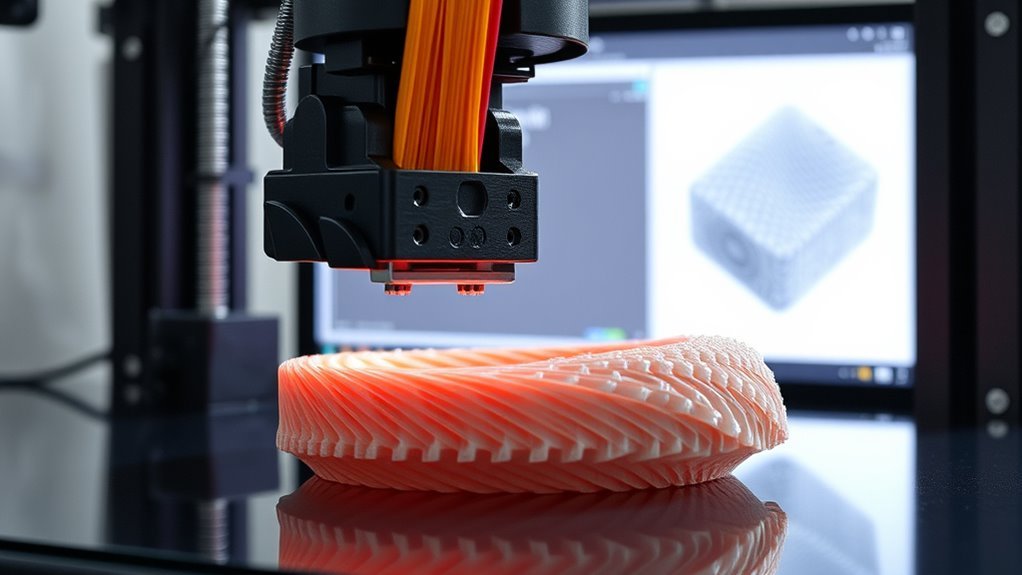
When converting CAD designs or 3D scans into printable files, you’ll first export the data into mesh formats like STL, OBJ, or 3MF. These formats represent the object’s surface with triangles or polygons.
Next, you use slicer software to prepare the model for printing. Here’s how it works:
- Import the STL or other mesh file and perform mesh repair to fix errors like holes or flipped normals.
- Choose a layer height to slice the model into thin horizontal layers.
- Generate G-code, which contains detailed printer instructions including nozzle movements and support structures.
- Optimize support structures and print orientation to guarantee strength and surface quality while minimizing material use.
This process turns your CAD or scanned model into a precise, printable file ready for your 3D printer. It’s pretty straightforward once you get the hang of it!
What Slicer Software Does to Prepare Your Model
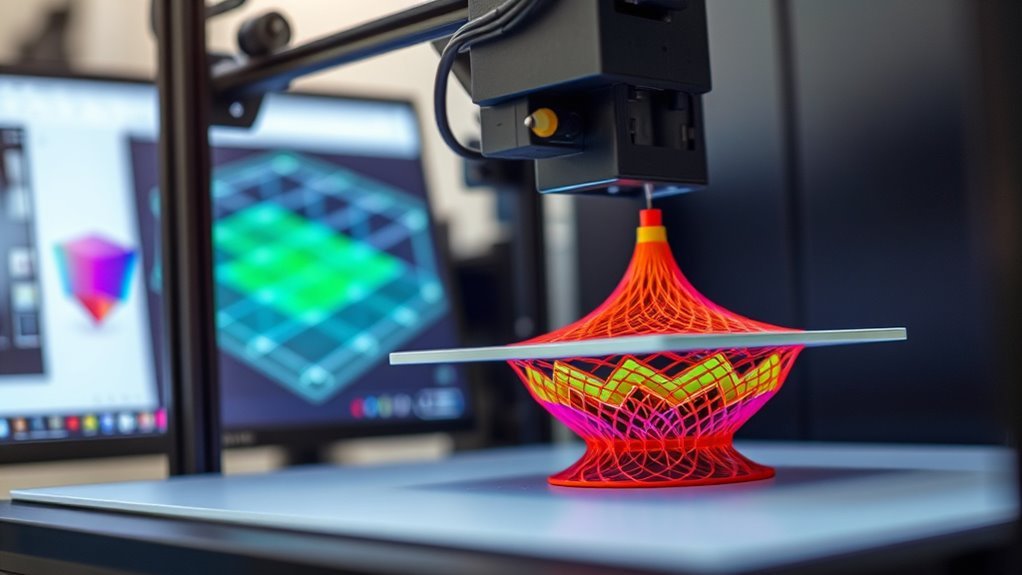
Slicer software transforms your 3D model into precise instructions your printer understands by breaking it down into thin horizontal layers. When you load your model into a slicer, it slices the mesh into layers based on your chosen layer height, then creates toolpaths for the printer’s nozzle to follow.
It converts these toolpaths into G-code, which controls movements, temperatures, and speeds. You set important parameters like infill percentage, shell count, and support generation to guarantee strength and print quality.
The slicer also analyzes part orientation to optimize printing efficiency and minimize defects. By preparing your model this way, the slicer guarantees your printer has clear, optimized instructions that balance detail, speed, and material use before the actual print begins.
How 3D Printing Instructions Are Generated Layer by Layer
Because every 3D print builds up layer by layer, your printer needs detailed instructions for each one. Slicing software breaks your 3D model into thin horizontal layers and generates precise commands.
Here’s how those instructions form:
- The slicer converts the model into G-code, specifying X/Y/Z moves, temperature, and speeds.
- For filament extrusion, G-code controls nozzle paths, feed rates, and layer height to deposit exact bead widths.
- Resin printers use resin masks to guide UV exposure patterns for each micrometer-thick layer.
- Powder bed printers create instructions for spreading powder and directing energy beams to fuse material selectively.
Your printer’s firmware reads these layer-by-layer commands, coordinating motion and extrusion or light intensity until the whole object is built.
How 3D Printing Technologies Use Your Data
When you send a 3D model to your printer, slicing software converts it into detailed instructions your machine can follow. These printable files include precise toolpaths, temperatures, and speeds tailored to your specific printer technology.
Your printer then interprets this data to control every movement and material action needed to build your object layer by layer. It’s pretty cool how it all comes together, right?
Data to Printable Files
To get your 3D model ready for printing, you’ll start by exporting it from CAD software or a 3D scanner into a mesh file format like STL, OBJ, or 3MF. These formats represent your object’s surface as a watertight triangular mesh.
Then, the slicer software breaks this mesh into layers and generates the instructions your printer needs.
- The slicer converts layers into G-code or machine-specific commands, guiding nozzle or laser movements.
- It embeds process settings like layer height, print speed, and supports to control quality and strength.
- For resin or powder printers, exposure parameters or deposition maps replace simple extrusion commands.
- Advanced formats like 3MF include printer-specific metadata, enabling multi-material or full-color prints without losing detail.
Slicing Software Role
At the heart of 3D printing lies slicing software, which transforms your 3D model files into detailed layer-by-layer instructions that guide the printer’s every move. This software sets key parameters like layer height, infill density, and support generation while converting your design into G-code, the language your printer understands.
Advanced slicers use adaptive layer heights to optimize quality and speed. They also provide print time estimation so you know how long your project will take.
| Parameter | Role |
|---|---|
| Layer Height | Controls resolution and speed |
| Infill Density | Affects strength and weight |
| Support Generation | Adds removable scaffolding |
| Adaptive Layer Heights | Balances detail and efficiency |
Slicing software guarantees precise toolpaths, making sure your prints come out successful and efficient every time.
Printer Interpretation Process
Once your slicing software hands over the G-code or sliced data, the printer dives into interpreting each command to bring your model to life. The printer firmware reads the file, following exact layer-by-layer instructions derived from the slicer’s toolpaths.
Here’s how it works:
- For FFF/FDM printers, the G-code directs X/Y/Z movements, extrusion amounts, and temperatures to control filament deposition precisely.
- Resin printers process exposure instructions, managing UV light timing and platform motion to cure each layer.
- Powder and binder-jet systems use slice-based raster patterns, adjusting laser power or binder timing to fuse materials accordingly.
- The firmware synchronizes motion, extrusion, and curing tasks, ensuring each layer builds perfectly on the last.
This precise interpretation transforms 3D data into a tangible object, layer by layer. It’s pretty cool how digital commands turn into real, physical parts right before your eyes!
The Role of Support Structures in 3D Printing
Although 3D printing lets you create complex shapes, some designs need extra help to avoid sagging or collapsing during the build. That’s where support structures come in—they hold overhangs, bridges, and islands steady.
FDM printers use thermoplastic supports, often with a soluble support material for easy removal. SLA/DLP printers rely on thin resin towers, sized by slicer settings like touchpoint size, balancing stability and cleanup.
You control support parameters—density, overhang angle, XY/Z offsets—to optimize print success and finish quality. Poor support design can cause failure or waste material.
| Printer Type | Support Material | Key Slicer Settings |
|---|---|---|
| FDM | Thermoplastic/soluble | Overhang angle, density |
| SLA/DLP | Resin towers | Touchpoint size, orientation |
| Both | Temporary geometry | XY/Z offsets, interface layers |
How 3D Printers Translate Instructions Into Material Deposition
Support structures give your 3D print physical stability during fabrication, but the printer still needs precise instructions to build each layer accurately. It all starts with slicing software that cuts your CAD model into many layers and generates G-code.
This G-code tells the printer exact coordinates, extrusion amounts, and temperatures.
Here’s how your printer translates those instructions into material deposition:
- The firmware reads the G-code line by line, interpreting movements and commands.
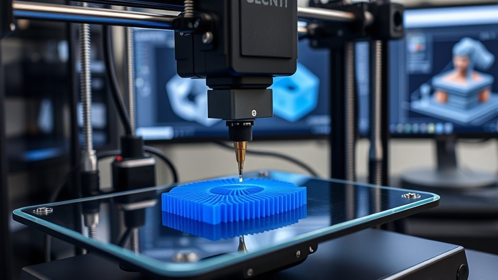
- Stepper motors move the extruder along X, Y, and Z axes layer-by-layer.
- The extruder heats and deposits the right volume of material based on extrusion commands.
- Sensors monitor position, temperature, and filament flow, adjusting or pausing if needed.
This precise coordination makes certain your model forms correctly, one layer at a time.
Why Post-Processing Depends on Your 3D Printing Workflow
Your post-processing steps change based on the materials you use and the printing technology behind them. Whether you handle finishing by hand or rely on automation depends on your production scale and workflow setup.
Understanding these factors helps you plan the right cleanup and finishing techniques for your parts. It’s all about matching your process to what works best for your specific needs.
Workflow Impact On Finishing
Because the post-processing steps hinge on your 3D printing workflow, understanding how technology, materials, and part design influence finishing can save you time and effort. Your finishing workflow depends heavily on factors like print orientation, layer height, and support removal, which directly affect how much sanding or smoothing you’ll need.
Material chemistry also plays a role, dictating whether parts require solvent cleaning, tumbling, or UV curing. Production volume further impacts your approach, as single prototypes often need hand-finishing, while larger runs benefit from automated processes.
Consider these workflow impacts:
- Choose print orientation and layer height to minimize support removal and post-processing time.
- Match material chemistry with compatible finishing methods for best results.
- Select technology aligned with your finishing capabilities.
- Scale finishing methods based on production volume for efficiency.
Material-Specific Post Steps
Although post-processing varies widely across 3D printing methods, understanding the specific steps tied to your chosen material can really streamline your workflow and improve the final part quality.
For example, resin prints need an IPA wash followed by resin post-curing. On the other hand, FDM parts often require support removal and annealing to boost strength.
Metal prints involve debinding and sintering, while powder-based prints demand depowdering and infiltration.
| Material Type | Key Post Steps | Purpose |
|---|---|---|
| Resin (SLA/DLP) | IPA wash, resin post-curing | Remove uncured resin, cure part |
| FDM/FFF | Support removal, annealing | Remove supports, relieve stress |
| SLS/MJF Nylon | Depowdering, infiltration | Clean powder, seal porosity |
| Metal Binder-Jet | Debinding and sintering | Achieve density, final strength |
Tailoring these steps guarantees peak surface finishing and durability. It’s all about knowing what your material needs after printing to get the best results.
Automation Versus Manual Tasks
When you choose a 3D printing workflow, the balance between automation and manual tasks shapes your post-processing experience. Your slicer software generates G-code automatically, but you’ll still tweak settings like orientation or support placement to guarantee quality.
Auto bed leveling and filament runout detection help reduce setup errors before printing even starts. These features make life a bit easier, right?
Most post-processing—removing supports, sanding, or UV curing—still requires hands-on work. It’s not all automatic, so be ready to get involved.
Automated depowdering and robotic material handling do exist in industrial setups, but they come with high costs. So, they’re not really an option for everyone.
Desktop FDM printers benefit most from low-cost automation. On the other hand, powder or metal printing demands more manual steps or expensive systems.
Understanding this balance helps you pick a workflow that fits your time, budget, and quality needs. It’s all about finding what works best for you.
Frequently Asked Questions
What to Look for With a 3D Printer?
You should look for gaps, layer height, wall thickness, and infill in the sliced file. Check temperatures, print speed, and support placement.
Also, review estimated print time, filament use, and the first-layer toolpath carefully. These details really help ensure your print comes out just right.
How Expensive Is 3D Printing as a Hobby?
You’ll spend around $300 starting with FDM printers and $500+ for resin setups. Consumables like filament or resin add ongoing costs, plus occasional replacements or upgrades.
It’s affordable but expect regular expenses for materials and maintenance. Just think of it like any other hobby—you’ll have to put in a bit to keep things running smoothly.
What Is the Biggest Problem With 3D Printing?
The biggest problem you’ll face with 3D printing is part strength anisotropy—layers bond weaker across interfaces, causing failures.
You’ll need to carefully choose orientation, material, and process to avoid weak spots and guarantee durability.
It’s all about making smart decisions to keep your prints strong and reliable.
Do You Have to Know How to Code to Use a 3D Printer?
You don’t need to be a coding wizard to use a 3D printer. Just like following a recipe, slicer software does the heavy lifting, turning models into instructions.
Conclusion
Now that you know how a 3D printer transforms digital dreams into real objects, imagine it as a silent artist, layer by layer, bringing your vision to life.
From your initial design to the final touch, every step is a precise dance of data and material. It’s pretty incredible how technology and creativity come together like that.
So, when you hit print, you’re not just making an object—you’re sparking creation itself. The 3D printer reads your digital design, translating it into thin layers that build up to form a tangible masterpiece.
In other words, 3D printing turns your ideas into reality right before your eyes. It’s a fascinating process where digital files guide the printer, ensuring every detail is captured perfectly. That’s how a 3D printer knows exactly what to print—by following the precise instructions encoded in your design, layer by layer.